Over the past two years, many cross-border sellers have repeatedly encountered the same issues:
They chose a “seemingly good-spec” generic magnetic power bank, only to face platform complaints for design infringement a few months after launch; or the product sold well initially but soon saw rising return rates due to overheating, slow charging, or poor compatibility.
The problem often lies not in marketing, but in underlying design capabilities.
Magnetic battery packs are not merely “battery + coil” products. They involve:
- Wireless charging structure
- Battery Management System (BMS)
- Fast-charging protocol handshake
- Thermal management design
- PCBA power architecture
If these capabilities are dispersed across different suppliers rather than integrated within one company, the final product usually ends up with one result:
Specifications look great on paper, but the real-world experience is poor.
Industry Landscape in 2026
- USB PD3.0 / PPS has become the mainstream fast-charging protocol.
- PD3.1 pushes power delivery to 140W–240W levels.
- Charging protocols for phones, tablets, and laptops are increasingly complex.
Implication: Power banks are no longer simple battery products—they are sophisticated power electronics.
If an OEM cannot control the entire chain from PCBA power architecture → fast-charging protocols → thermal management → structural design, the final product will likely remain only “functional,” not “stable and reliable.”
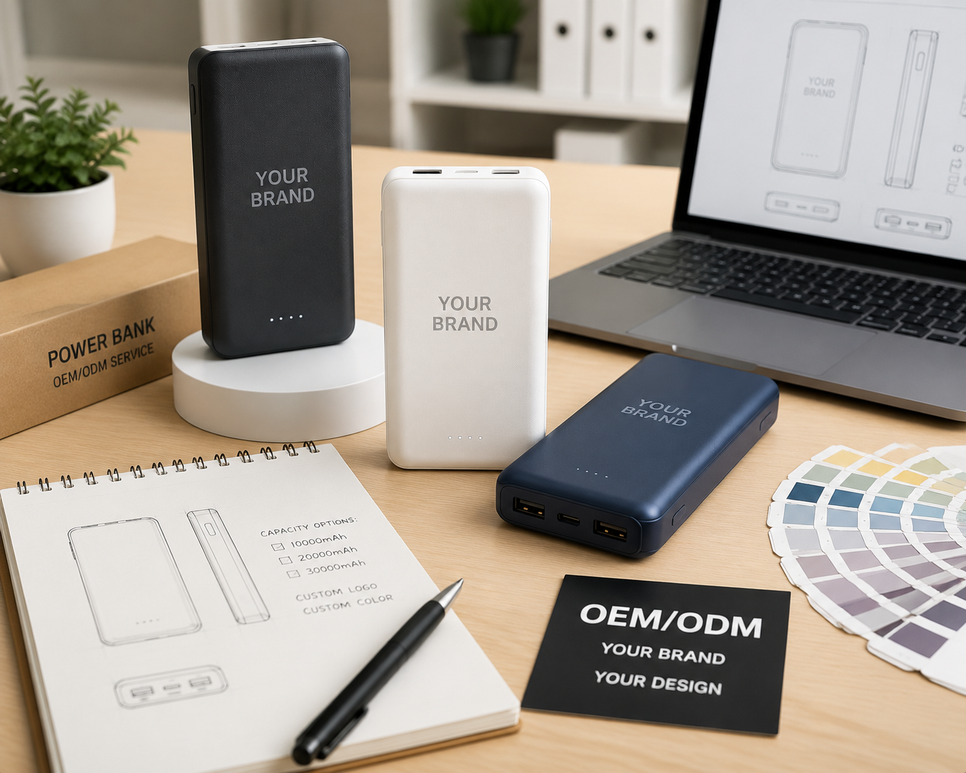
For the past 15 years, AOVOLT (Shenzhen ESC) has focused on transforming charging products from “assembly manufacturing” into “power system design.”
This explains why more brands now prioritize OEMs with vertically integrated R&D capabilities when sourcing magnetic battery packs.
Why Magnetic Battery Pack OEM Demand is Rising in 2026
The surge in magnetic battery pack demand is not because the product is “new,” but because mobile device power structures have changed.
Previously, smartphones had 3000–4000mAh batteries, and standard 5W–10W power banks sufficed. Today’s ecosystem is entirely different:
- iPhone / Android flagships typically support 20W–45W fast charging
- Tablets require 30W–65W charging
- Slim laptops increasingly use 100W USB-C power delivery
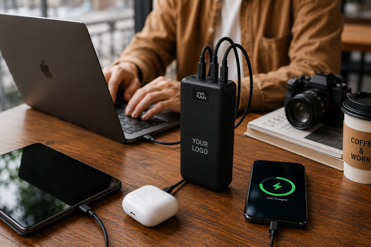
At the same time, mobile office usage is growing.
Magnetic battery packs are evolving from emergency devices to everyday power solutions, raising the technical threshold for brands.
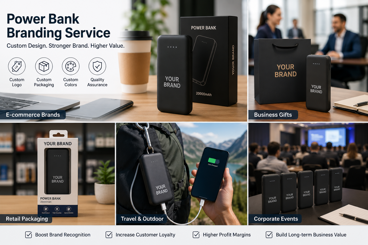
Key Considerations for Global Brands When Choosing Magnetic Power Bank OEMs
From actual OEM projects, price is not the primary concern. Brands focus on three main factors:
- Appearance risk
- Charging performance stability
- Global certifications
Typical Procurement Evaluation Logic
| Procurement Focus | Actual Risk | OEM Capability Requirement |
|---|---|---|
| Appearance Design | Generic design infringement / platform complaints | Independent ID design & mold capability |
| Fast-Charge Compatibility | Phones unable to trigger fast charge | Multi-protocol fast-charge PCBA design |
| Heat Management | Negative reviews / high return rates | Power architecture & thermal design |
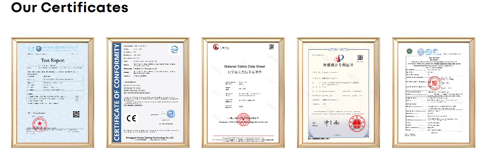
| Certification | Customs or platform restrictions | CE / FCC / RoHS / UN38.3 |
Many OEMs only address the last point—contract manufacturing.
However, the factors that truly affect user experience are power design and fast-charging protocol capability.
Why Multi-Protocol Fast Charging is a Core Requirement
Many products claim to “support fast charging,” but engineers ask:
Which protocols are supported?
Mainstream mobile devices use various fast-charging protocols, including:
- PD3.0 / PD3.1
- PPS
- QC3.0
- FCP
- SCP
- AFC
- Apple 2.4A
- BC1.2
These protocols exist because different brands adopt different charging control logic. A power bank supporting only basic PD may cause phones to downgrade to 5V or 9V charging. Users then experience:
“Fast charging claimed, but charging is slow.”
For example, USB PD3.0’s PPS (Programmable Power Supply) dynamically adjusts voltage and current during charging to match battery demand, reducing energy loss and heat.
| Protocol | Voltage Control | Efficiency | Temperature |
|---|---|---|---|
| Standard PD | Fixed voltage | Lower | Higher |
| PD + PPS | Dynamic voltage matching | Higher | Stable |
Traditional PD only provides fixed voltage levels (5V / 9V / 15V / 20V), while PPS can finely tune between 3.3V–21V in 20mV steps, crucial for high-power devices.
Key takeaway: PCBA must support full protocol handshake logic to achieve effective fast charging. Smart fast charging PCBA for you: Maximize the efficiency and safety of electronic products.
PCBA Power Architecture is Central to Fast Charging Experience
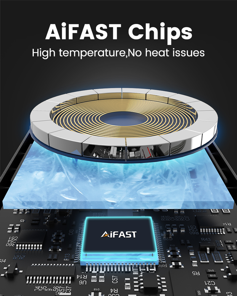
Many brands overlook that heat issues are not merely structural—they are power-related.
When charging protocols mismatch, devices perform additional voltage conversions, generating extra heat:
- PD fixed voltage → internal phone step-down
- PPS dynamic voltage → phone matches battery directly
This efficiency gap explains why proper PCBA power design is essential.
AOVOLT’s magnetic battery projects focus on three core modules:
- Multi-protocol fast-charge chip solutions
- Dynamic power management architecture
- Battery BMS & temperature control logic
These modules determine if a product can deliver “factory-level charging speed + low-temperature operation.”
Manufacturing System Determines OEM Project Success
When entering mass production, the challenge is not sample parameters but whether the manufacturing system is complete.
Common mass-production issues include:
- Unstable charging efficiency
- Magnetic structure assembly errors
- Shell tolerance affecting wireless charging efficiency
- Variance in thermal performance across batches
These problems often arise from fragmented supply chains:
| Component | Supplier |
|---|---|
| Shell | Factory A |
| PCBA | Factory B |
| Assembly | Factory C |
Even small deviations can affect final performance. Vertically integrated factories improve consistency by handling:
R&D → Mold Opening → Injection Molding → Hardware Integration
15 Years of Manufacturing Experience: Complete Chain from R&D to Mass Production
AOVOLT’s manufacturing system leverages 15 years of power electronics experience, with the core base in Dongguan, a global consumer electronics hub.
Manufacturing Stages
- R&D: Product Design & Power Architecture
- Focus on fast-charge protocol architecture, PCBA topology, and BMS design
- Addresses multi-protocol compatibility, power efficiency, thermal stability
- Engineering validation: protocol triggering, power efficiency, long-load thermal tests
- Mold Opening: High-Precision Mold Development
- Critical for wireless coil distance accuracy (<0.3mm tolerance)
- Ensures shell tolerance, magnet ring alignment, and heat dissipation
- Injection Molding: Consistent Production
- Controls plastic stability, molding temperature, shrinkage
- Ensures shell uniformity, magnet module positioning, and assembly efficiency
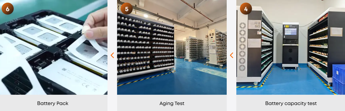
- Hardware Integration: Assembly & Testing
- Includes PCBA installation, battery assembly, magnetic module installation
- Tests: fast-charge protocol, power output, thermal rise, aging
| Test Type | Purpose |
|---|---|
| Fast-Charge Protocol | Verify PD / PPS / QC triggering |
| Power Output | Confirm rated power stability |
| Thermal Rise | Monitor long-term charging temperature |
| Aging | Validate long-term stability |
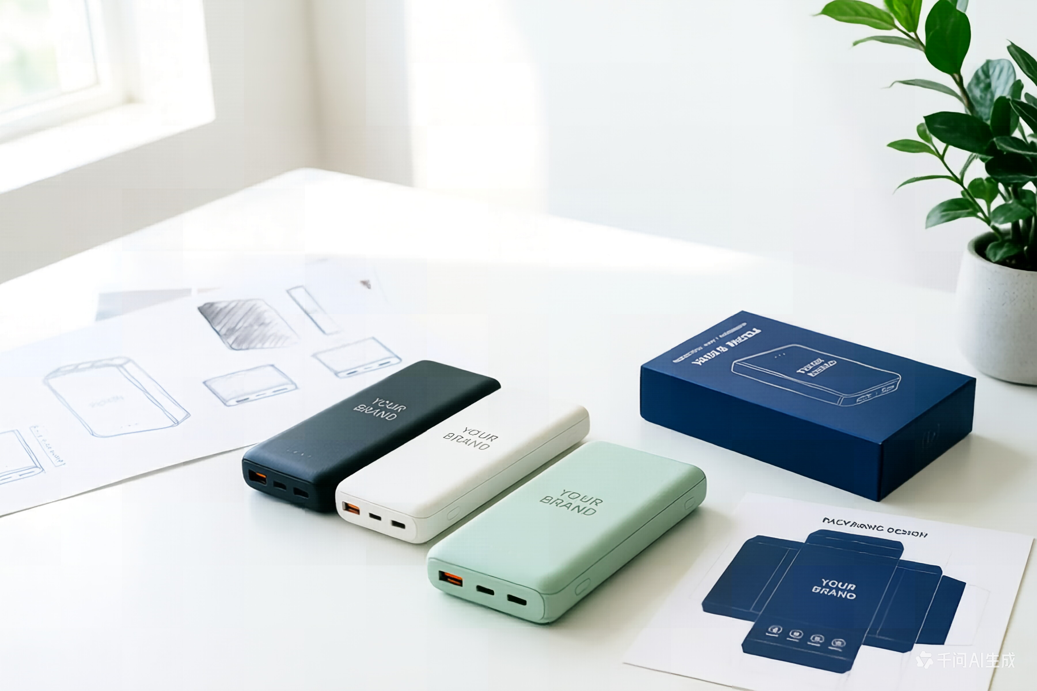
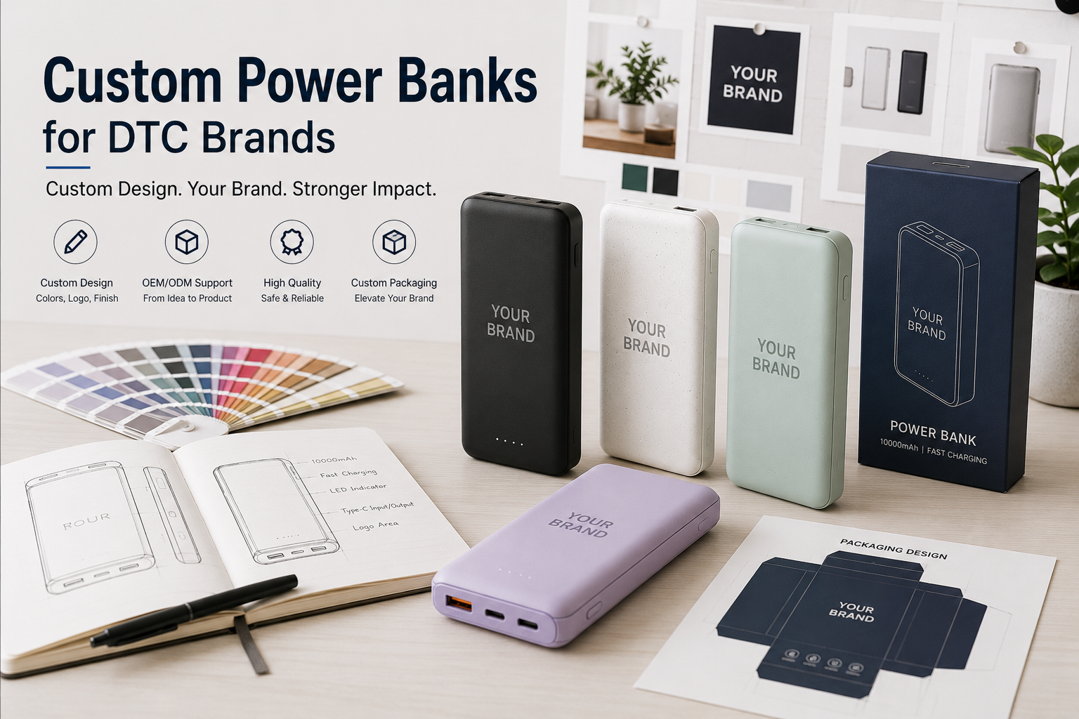
Value for Cross-Border Sellers: Avoid Appearance Infringement
Magnetic battery packs face appearance infringement risk—many use the same generic structures.
Platform enforcement can include:
- Product delisting
- Account risk
- Inventory freezing
AOVOLT’s OEM projects offer:
- Unique exterior designs
- Independent structural development
- Exclusive molds
This reduces platform infringement risk, often more critical than price for cross-border sellers.
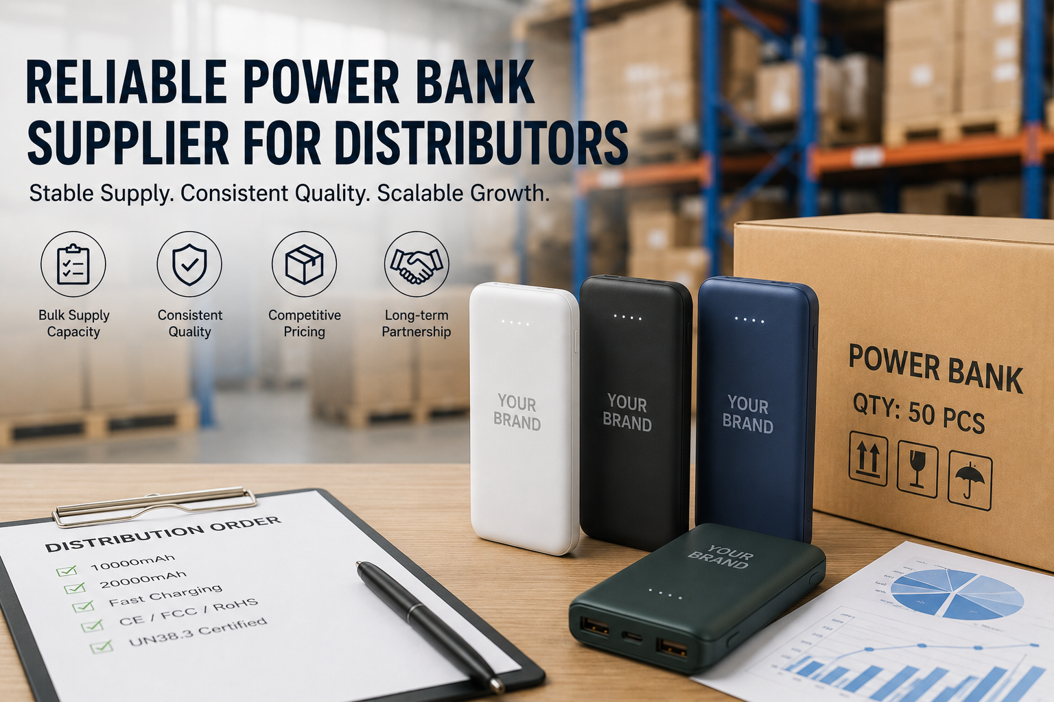
Value for Brands and B2B Traders: Faster Lead Times & Stable Supply
Source factories controlling key stages—mold production, injection lines, PCBA, assembly—deliver:
- Fast lead time: no cross-supplier coordination required
- Stable mass production: rapid scaling per order volume
Essential for global B2B distributors.
FAQ: Magnetic Battery Pack OEM
Q: Required certifications?
| Market | Common Certifications |
|---|---|
| Europe | CE / RoHS |
| USA | FCC |
| Japan | PSE |
| Global Shipping | UN38.3 / MSDS |
Q: Can they support fast charging?
Yes, with complete protocol support: PD3.0, PPS, QC3.0, AFC, FCP, SCP, Apple 2.4A, BC1.2.
Q: Typical MOQ?
- Standard OEM: 1000–3000 pcs
- Custom design: 3000–5000 pcs
Q: Suitable for branded products?
Yes—this growing category rewards unique design and stable performance.
Q: Typical OEM development cycle?
- Product design & PCBA: 3–4 weeks
- Mold development & structure testing: 4–6 weeks
- Mass production prep & certification: 3–4 weeks
- Total: ~10–12 weeks
Conclusion: Choosing an OEM is Choosing Supply Chain Capability
Magnetic battery packs involve:
- Power electronics design
- Fast-charging protocol control
- Battery management system
- Wireless charging structure
- Precision manufacturing
AOVOLT integrates these within a complete closed-loop system from PCBA R&D → mold → injection → assembly, ensuring product quality and stable supply chains.
For brands, cross-border sellers, and global distributors, a partner with full R&D and manufacturing capabilities means lower project risk and longer product lifecycle.
As sales scale, the value of a capable supply chain becomes increasingly clear—explaining why brands now prefer OEMs with PCBA R&D expertise and vertically integrated manufacturing.
References: