In the consumer electronics supply chain, purchasing decisions for Custom PCBA for Apple 2.4A protocol are often oversimplified as mere stacking of resistor performance. This is actually a major cognitive trap. For B2B buyers pursuing high reliability, the core solution for Apple devices (such as iPads or older iPhones) failing to handshake at full 2.4A under USB-A interfaces does not lie in increasing power. Instead, it depends on whether the Voltage Bias Logic on the D+/D- data lines achieves industrial precision within ±5%.
If your PCBA prototype for power adapters cannot stably output bias voltages of 2.7V and 2.0V during load tests, end users will face the awkward scenario of charging current being limited to 0.5A.
Key Conclusion: Cost Range and Procurement Insights
A mature circuit solution supporting the Apple 2.4A protocol and equipped with Smart Power Allocation PCBA logic, on SMT assembly for chargers lines in Dongguan or Shenzhen, typically ranges from $1.65 to $3.80 per board for MOQ of 5K–10K units.
Schemes below this price usually compromise on ESR values of filter capacitors or the saturation current of power inductors, directly indicating potential high repair rates.
Technical Logic Behind Apple 2.4A Protocol Recognition
Why does stable Apple 2.4A recognition remain the technical core of car chargers, public charging stations, and high-end power strips, even with USB-C PD widely adopted today?
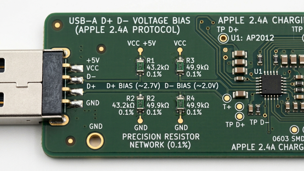
Decoding D+ and D- Voltage Divider Circuits
Apple 2.4A is not based on digital handshake protocols but relies on analog level detection. Specifically, the adapter must provide specific voltages on the USB-A data pins:
- D+ Pin: Approximately 2.7V
- D- Pin: Approximately 2.0V (may be reversed depending on specific chip logic)
When the Apple device's charging IC detects this specific D+/D- voltage bias logic, it raises the current input limit. Using ordinary 5% precision resistors in a custom PCBA, however, makes handshake failures highly likely due to voltage fluctuations caused by temperature drift.
From Passive Voltage Dividers to Active Control ICs
Traditional approaches use precise resistor arrays for voltage division. Modern high-performance solutions prefer integrated USB-A charging controller ICs. These chips not only simulate Apple 2.4A but also maintain downward compatibility with BC1.2 compliance.
Advantages:
- Dynamically senses device connection
- Seamlessly switches between Apple protocol and Android DCP (Dedicated Charging Port) modes
Risks:
- Numerous low-quality counterfeit chips exist
- High quiescent current leads to noticeable heat even at no-load
Choosing a Scheme: Passive Voltage Divider vs Active Recognition IC
The following comparison highlights engineering redundancy vs cost trade-offs:
| Technical Metric | Basic (Resistor Divider) | Professional (Smart IC) | B2B Procurement Recommendation |
|---|---|---|---|
| Protocol Recognition | Apple 2.4A only (fixed) | Multi-protocol identification chip | Prefer active IC for diverse devices |
| Standby Power (No-load) | High (leakage through resistors) | Very low (auto sleep mode) | Meets EU ErP Lot 6 standby energy standards |
| Voltage Precision Stability | Large drift with temperature | Internal reference voltage source locked | Critical for preventing handshake degradation at high temperatures |
| PCB Space | Occupies many resistor positions | Highly integrated, SOT-23 or smaller | Suitable for ultra-compact car charger PCBA |
| ESD Protection | Weak | Integrated ≥8kV | Reduces risk of board damage from static discharge |
Core Engineering Challenges in High-Current PCBA Design
Designing for 2.4A output (≥12W per port) increases PCBA difficulty exponentially. This involves efficient electronic flow management rather than simple connectivity.
Compact Thermal Management
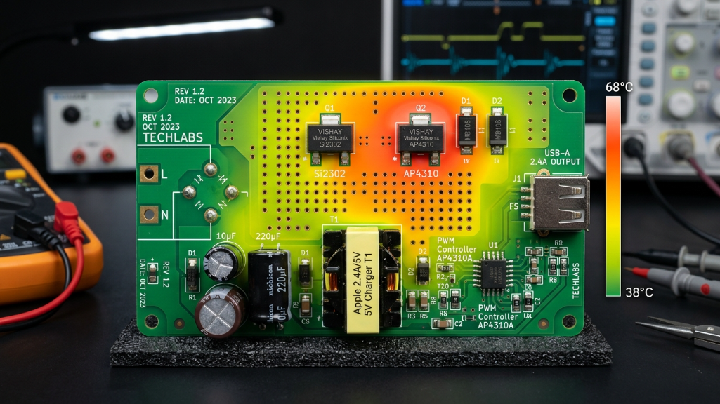
Thermal management in power electronics is the gold standard for product half-life. On Apple 2.4A custom boards, the AC-DC synchronous rectification (SR) section generates the most heat.
Layout Techniques:
- Increase copper thickness to 2oz or even 3oz
Heat Path:
- Place multiple vias under MOSFETs to transfer heat to a large copper layer, avoiding reliance on fragile enclosure dissipation
Ripple Noise Suppression and Device Longevity
Apple charging ICs are extremely sensitive to input current purity. If ripple exceeds 150mV, high-frequency noise can interfere with capacitive touchscreens, causing “ghost touches” during charging.
Case Study:
A North American high-end hotel furniture supplier experienced 280mV ripple at 2.4A due to low-cost electrolytic capacitors. After redesigning PCB layers, distancing feedback loops from inductive interference, and introducing high-frequency ceramic capacitor suppression, ripple was reduced to ≤60mV, resolving all repair issues.
ESD Circuit Design and Compliance
USB-A interfaces are vulnerable to electrostatic discharge. Relying solely on the chip's internal protection is insufficient. Designs typically include TVS diodes on D+/D- lines with minimal grounding impedance, ensuring compliance with IEC 61000-4-2 laboratory tests.
Manufacturing Excellence: From Schematic to SMT Assembly
Even perfect schematics become electronic waste if the factory quality control is poor. SMT assembly precision directly impacts Apple 2.4A protocol stability. Provide you with Samsung 45W Super Fast Charge 2.0: Genuine B2B OEM Guide.
- Component Selection: Avoid refurbished ICs; low-quality MOSFET Rds-on rises quickly at 2.4A, causing overheat
- Solder Paste & Process: Ensure ≥75% pin coverage for high-current reliability
Advanced Protocol Coordination: Apple 2.4A and Modern USB-C PD
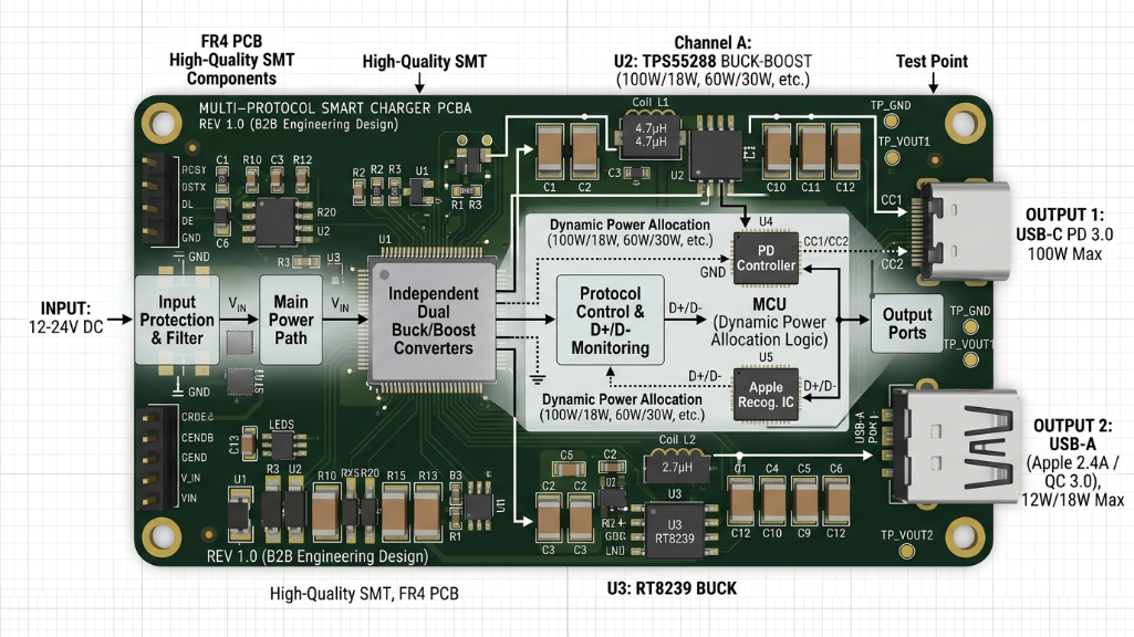
Previously, stable Apple 2.4A output required only precise bias resistors. Today, with multi-protocol integration, smart power allocation across USB-A and USB-C ports is crucial.
When a user connects an iPad (Apple 2.4A) and MacBook (PD 3.0) simultaneously, the Smart Power Allocation PCBA logic must complete power handshake in milliseconds. Immature MCU firmware may cause A-port connection to restart C-port or reduce A-port to 5V/1A.
Solution: Use independent dual-channel buck rather than low-cost parallel sharing.
B2B Reference: Multi-Protocol Power Allocation Strategies
| Connection Scenario | USB-C Output | USB-A Output (Apple 2.4A) | Efficiency | Key Technology |
|---|---|---|---|---|
| Single A Port | N/A | 5V / 2.4A (12W max) | >88% | D+/D- high-precision bias detection |
| Single C Port | PD 65W max | N/A | >92% | GaN power devices, high-frequency switching |
| A + C Simultaneous | 45W (fixed) | 5V / 2.4A (12W stable) | >85% | Dynamic power sharing |
| No-load Standby | <0.1W | <0.1W | N/A | Static consumption & loop compensation optimization |
Vertical Integration Advantage: Why Source Factories in Dongguan?
In bulk procurement of Custom PCBA for Apple 2.4A protocol, circuit design is only part of the story. Reliability is 40% solution, 60% production determinism.
AOVOLT, with 15 years in consumer electronics manufacturing, leverages heavy-asset vertical integration in Dongguan. Custom requirements are completed within one industrial park, from industrial design, R&D, to mold opening.
Technology Barriers & Full Protocol Coverage
AOVOLT’s fast-charging PCBA exceeds 140W and supports all major protocols: BC1.2, Apple 2.4A, AFC, PD 3.0, PPS, QC 3.0, Huawei SCP/FCP. This ensures high handshake success across global devices.
Closed-Loop Supply Chain: Mold to Hardware Integration
Internal injection molding and hardware integration allow simultaneous PCB shape and mold heat dissipation optimization, critical for ultra-thin magnetic power banks achieving 2.4A output.
FAQ: 5 Core Questions on Apple 2.4A Custom PCBA
Q1: Why does my PCBA labeled 2.4A only charge iPad at 1A or less?
A1: D+/D- voltage bias logic deviation. If voltage deviates from 2.7V/2.0V ±5%, the device limits current as an unsafe third-party accessory. Solution: higher-precision resistors or active recognition chip.
Q2: Does PCBA size affect Apple 2.4A recognition?
A2: Smaller size increases routing density. EMI interference can distort waveform. Shielding layers and optimized copper planes balance compactness with protocol stability.
Q3: How many layers for high-current 2.4A output?
A3: 4-layer boards recommended for independent power and ground planes, reducing ripple noise and protecting Apple battery health.
Q4: How to implement auto-switching between Apple 2.4A and Android fast charging?
A4: Use multi-protocol identification chip to dynamically detect devices and adjust voltage or handshake.
Q5: Typical lead time for bulk PCBA?
A5: Mature boards: 10–15 days SMT assembly. Custom mold or complex circuit: 30–45 days. Vertical integration accelerates delivery.
Conclusion: Engineering Certainty Against Market Fluctuations
Custom PCBA for Apple 2.4A protocol is no longer a pure technical barrier but a litmus test for manufacturing reliability and quality control granularity.
Support for this protocol involves ripple noise suppression, thermal management, and ESD protection—all foundational engineering elements.
For B2B buyers, selecting a supplier is not just about BOM comparison but choosing a partner with risk resistance.
Whether for high-density power bank PCBA or industrial 140W fast-charging boards, AOVOLT adheres to strict standardized QC, rapid delivery, and high-end custom design. In Dongguan, the approach is not just SMT assembly but heavy-asset, fully integrated production, delivering power solutions with unique identification and high technical barriers.
In the future hardware ecosystem, only factories that pursue extreme precision in protocol details and achieve deep vertical supply chain integration will become the most reliable B2B technical partners.
References: